Tại sao Bạn nên chọn Sieuthidientudong.com ? \=> Giá cạnh tranh so với thị trường. \=>Nói không với hàng nhái. 100% chính hãng. \=> Bảo hành 12 tháng theo nguyên tắc 1 đổi 1. \=> Thời gian đáp ứng nhanh, giao hàng tận nơi. \=> Tư vấn giải pháp Miễn Phí 24/24. Bộ Điều Khiển Nhiệt Độ FUJI PXR9NEA1-0V000 Điện áp : 100-240VAC Ngõ vào : RTD, Pt100 ohm, 3-wire type (°C) Ngõ ra 1 : 4-20mA DC output Ngõ ra 2 : Relay contact output Nhiệt độ làm việc : -10 to 50°C Kích thước : 96x96mm Sản Phẩm Cùng Loại Mã Hàng Bộ điều khiển nhiệt độ FUJI PXR9BEC1-0V000 Bộ điều khiển nhiệt độ FUJI PXR9NEA1-0V000 Bộ điều khiển nhiệt độ FUJI PXR9TAA1-0VM00 Bộ điều khiển nhiệt độ FUJI PXZ4TAY2-0V000 Bộ điều khiển nhiệt độ FUJI PXR9NEA1-8W000-C Bộ điều khiển nhiệt độ FUJI PXR4BCR1-0V000-C Bộ điều khiển nhiệt độ FUJI PXR9NEA1-FV000 Bộ điều khiển nhiệt độ FUJI PXR9NER1-FV000 Bộ điều khiển nhiệt độ FUJI PXR5-NEA1-8B000 Bộ điều khiển nhiệt độ Fuji PXR4 ( 48mm x 48mm ) 1/16 DIN là dòng sản phẩm có kích thước nhỏ gọn, số lượng đầu ra đa dạng, khả năng chịu được thời tiết với tiêu chuẩn IP66 cùng nhiều đặc điểm tối ưu khác mà bạn nên tìm hiểu thêm. Đặc điểm của bộ điều khiển nhiệt độ Fuji dòng PXRĐối với những ai đã từng sử dụng bộ PXR4 thì chắc chắn rằng ít nhiều cũng đã đánh giá được những tính năng ưu việt mà nó đem lại rồi. Mình muốn chia sẻ thêm một vài điều để cho bạn nào có nhu cầu chuyển đổi hoặc mua mới về lắp đặt có thể tham khảo thêm. - 1. extremely compact temperature controller which has 48 x 48 mm front panel with a large, white LCD and 58- mm depth behind panel. Developed as a successor to the standard model PXR, PXF4 features fast sampling speed (50 ms) equal to PXH, highly accurate input indication, and universal input, in addition to various functions of PXG, while achieving a competitive price. Equipped with multiple input/output and sophisticated con- trol functions, PXF4 serves as a suitable temperature con- troller for a wide range of use. FEATURES 1. Enhanced control performance which makes PXF suitable for a wide range of application • Fast sampling speed of 50 ms (cf. PXH: 50 ms, PXR: 500 ms) • Improved input indication accuracy For example: indication accuracy when measuring around 0.0°C by using type K thermocouple of which measuring range 0.0 to 400.0°C: ±1.1°C (cf. PXR: ±3.1°C) • Freely configurable control cycle (100 ms to 99 s) • Control method selectable among 7 types (ON/OFF control, PID control, fuzzy PID control, self- tuning control, PID2 control, 2-degrees-of-freedom PID control, motorized valve control) 2. Any type of input can be accepted • Universal input is supported (thermocouple, RTD, volt- age, current) • Control output is selectable among 4 types (Relay con- tact, SSR drive, current linear, voltage linear) The following optional functions can be incorporated: • 1 digital input (up to 3 digital inputs for motorized valve control version), and up to 3 digital outputs • Remote SV input, analog re-transmission output • Motorized valve control output • Current monitoring using CT 3. Easy-to-see clear display and user-friendly interface • Wide viewing angle, high luminance white LED backlit LCD • Large PV display (with character height of 15.3 mm which is the highest in the market) • Easy-to-distinguish parameter display with screen num- bers • Easy-to-identify 11 segment alphanumeric display • Digit select key for easier value-setting (5 keys) 4. Most compact design in the market • Approx. 30% reduction in size compared to conventional models. (58 mm depth behind panel) DATA SHEET PXF4-2 EDS11-178a MICRO-CONTROLLER X (48 × 48 mm) MICRO-CONTROLLER X Date Jun. 10, 2015 PX series Digital Temperature Controller 5. A variety of functions extending the possibility of tempera- ture controller • 64 steps ramp/soak function • 8 PID setting pallets, 8 SV pallets, zone PID facilitate frequent change of control conditions • Loader interface provided as standard (Power can be supplied via loader cable. Loader software is available from our HP for free of charge) • RS485 communication (optional) capable of coopera- tive operation, programless communication SPECIFICATIONS 1. General specifications Power supply: 100 V (-15%) to 240 V (+10%) AC, 50/60 Hz; 24 V (±10%) DC/AC Power consumption: 10 VA MAX. (100 to 240 V AC), 3 VA MAX. (24 V DC/AC) Insulation resistance: 20 MΩ or more (at 500 V DC) Withstand voltage: Power source ↔ all terminals: 1500 V AC for 1 min Relay contact output ↔ all terminals: 1500 V AC for 1 min Between others 500 V AC for 1 min 2. Input section 2.1 Process value input Number of input: 1 Input setting: Programmable scale Input signal: See Table 1 (Universal input: thermocouple, RTD, voltage, current) Standard measurement range and input type: See Table 1
- 2. Ta = 23°C): • Thermocouple input: either ±1°C ±1 digit or ±0.3% ±1 digit of indicated value, whichever is larger *except: Thermocouple B: 0 to 400°C: no accuracy assurance Thermocouple R: 0 to 500°C: ±3°C ±1 digit Thermocouples K, T, E, U, or N: -200 to -100°C: ±2°C ±1 digit • RTD input: ±0.8°C ±1 digit or ±0.2% ±1 digit of indicated value, whichever is larger • mV input, voltage input, current input: ±0.3%FS ±1 digit Temperature effect on sensitivity: ±0.3%FS/10°C Indication resolution: See Table 1 Input sampling rate: 50 ms Input impedance: • Thermocouple, mV input: 1 MΩ or more • Current input: 150 Ω or less (built-in diode) • Voltage input: About 1 MΩ Variation by signal source resistance: • Thermocouple, mV input: ±0.3%FS ±1 digit per 100 Ω • Voltage input: ±0.3%FS ±1 digit per 500 Ω Allowable wiring resistance: RTD: 10 Ω or less (per wire) Allowable input voltage: • DC voltage input: within ±35V • Current input: within ±25 mA • Thermocouple, RTD, mV input: within ±5 V Noise reduction ratio: • Normal mode: 40 dB (50/60 Hz) • Common mode: 120 dB (50/60 Hz) • Between input and power supply: ±1°C at 220 V AC, 50/60 Hz Input correction: (a) User adjustment: ±50%FS for each of zero and span point (b) Process value shift: ±10%FS (c) Input filter: 0.0 to 120.0 sec (filter OFF if set at 0.0) (d) Square root extraction: -0.1 to 105% (OFF if set to -0.1%) Overrange, underrange: Beyond range of -5 to 105% (accuracy not guaranteed between -5 and 0, and between 100 and 105%FS) *Pt (-200 to 850°C) input: out of the range between -2 to 105% 0 to 10 V DC input: out of the range between -2 to 105% Thermocouple E input: out of the range between -5 to 102% 2.2 Remote SV input (optional) Number of inputs: 1 Input signal: Voltage: 0 to 5 V DC /1 to 5 V DC/0 to 10 V DC, Current: 0 to 20 mA DC/4 to 20 mA DC (a 250Ω resistor is required for current input) Input impedance: About 1 MΩ Sampling rate: 50 ms 2.3 Current transformer (CT) input (optional) Input type: Single phase CT, 1 point For 1 A to 30 A: CTL-6-S-H For 20 A to 100 A: CTL-12-S36-8F Range of detected current: 1 A to 100 A Detected current accuracy: Setpoint ±5% FS Detected current resolution: 0.1 A ON time necessary for detection: 300 ms MIN. 2.4 Digital input (DI) (optional) Number of points: Up to 1 (Up to 3 digital inputs for motorized valve control version) Specifications: No-voltage contact or transistor input Contact capacity: 5 V DC, about 2 mA (per point) Input judgment: ON voltage: 2 V DC or lower OFF voltage: 3 V DC or higher Sampling pulse width: 50 ms MIN. Functions: Remote mode selection, SV changeover, control standby, AT startup, timer startup, alarm unlatch, program selec- tion, start/stop/reset, PID switching (normal/reverse), etc. 3. Output section 3.1 Control output Number of points: Up to 2 (2 points: Heating/cooling control) Type: selected among (1) to (6) below (1) Relay contact output (SPST) • Proportional cycle: 1 to 150 sec • Contact structure: SPST (single pole single throw) • Contact capacity: 250 V AC/30 V DC, 3 A (resistive load) • Minimum ON/OFF current: 10 mA (5 V DC) • Mechanical life: 20 million operations MIN. (100 operations/min) • Electrical life: 100,000 operations MIN. (rated load) (2) Relay contact output (SPDT) • Proportional cycle: 1 to 150 seconds • Contact structure: SPDT (single pole double throw) • Contact capacity: 250 V AC/30 V DC, 5 A (resistive load) • Mechanial life: 50 million operations MIN. (100 operations/min) • Electrical life: 100,000 operations MIN. (rated load) (3) SSR/SSC drive output • Proportional cycle: 1 to 150 sec • ON voltage: 12 V DC (between 10.7 and 13.2V DC) • OFF voltage: 0.5 V DC or lower • Maximum current: 20 mA DC • Load resistance: 600 Ω MIN. (4) Current output (0 to 20 mA DC/4 to 20 mA DC) • Accuracy: ±5%FS • Load resistance: 500 Ω MAX. (5) Voltage output (0 to 5 V DC/1 to 5 V DC/0 to 10 V DC/2 to 10 V DC) • Accuracy: ±5%FS • Load resistance: 10 kΩ MIN.
- 3. control output • Contact structure: 2 SPST contacts without interlock circuit *SPST: Single Pole Single Throw • Contact capacity: 250 V AC/30 V DC, 3A (resistive load) • Mechanical life: 20 million operations MIN. (100 operations/min) • Electrical life: 100,000 operations MIN. (rated load) 3.2 Alam output (optional) Number of outputs: Relay contact output: Up to 3 (shared common) Up to 2 (independent common) Output specifications: Relay contact output Contact structure: SPST (single pole single throw) Contact capacity: 250 V AC/30 V DC, 1 A (resistive load) Minimum ON/OFF current: 10 mA (5 V DC) Mechanical life: 20 million operations MIN. (100 operations/min) Electrical life: 100,000 operations MIN. (rated load) Output functions: Alarm output (see “Alarm function”), main unit control mode output, program status output, control output 1 and 2, etc. Output cycle: 100 ms 3.3 Re-transmission output (optional) Number of points: 1 Type: Current/voltage output (0 to 20 mA DC/4 to 20 mA DC/0 to 5 V DC/1 to 5 V DC/ 0 to 10 V DC/2 to 10 V DC) • Guaranteed output range: 0 to 21.0 mA DC/0 to 10.5 V DC • Accuracy: ±0.2%FS (±5%FS at 1 mA or smaller) • Resolution: 10,000 MIN. • Load resistance: 500 Ω MAX. (current), 10 kΩ MIN. (voltage) Output cycle: 100 ms Output contents: PV, SV, DV, MV Additional function: Scaling function 4. Indication/setting section 4.1 Display unit Type: LCD (with backlight) Indication contents: Process value indication: 11-segment, 4-digit [white] Setpoint indication: 11-segment, 4-digit [green] Screen No. indication: 7-segment, 3-digit [orange] Indication status: 23 indicator lamps Luminance setting: possible (4 steps) 4.2 Setting section Type: Sheet type keys (with emboss) Number of keys: 5 keys 5. Control functions 5.1 Control types ON/OFF control PID control • Dual control (heating/cooling) • PID parameters determination: Auto tuning Fuzzy PID control • Dual control (heating/cooling) • PID parameters determination: Auto tuning Self tuning control PID2 control • Dual control (heating/cooling) • PID parameters determination: Auto tuning 2-degrees-of-freedom PID • PID parameters determination: Auto tuning Position proportional PID (servo) control without posi- tion feedback • Full stroke time: 30 seconds MIN. 5.2 Control parameters • Proportional band (P): 0.1 to 999.9% • Integral time (I): 0 to 3200 sec. Integral time control invalidated when I = 0. • Differential time (D): 0.0 to 999.9 sec. Differential time control invalidated when D = 0. • Control cycle: 100 to 900 ms (in 100 ms), 1 to 99 s (in seconds) • Anti-reset windup: 0 to 100% of measurement range • Hysteresis band: 50% of measurement range (at 2-position control only) • Number of SV and PID combinations: 8 combinations. Changed by any of parameter setting, digital input, communication, user function keying, zone change. 5.3 Control mode Mode type: Auto, Manual, Remote * During 2-position control in Manual mode, 2-position manual operation with MV = 100% or 0% is operated. Mode switching: • Auto↔Manual: Balanceless·bumpless • Auto/Manual → Remote: Balance·bumpless • Auto/Manual ← Remote: Balance·bumpless 6. Alarm function 6.1 Number of alarm setting points 3 points 6.2 Alarm type Process value (upper limit/lower limit, absolute/deviation, range), main unit error, etc. (non-excitation, delay, latch, timer function option pro- vided) 6.3 Heater current alarm function (optional) *Current detector (CT) is to be prepared separately (see page 7.) Detectable range: 1 A to 100 A Detected current resolution: 0.1 A Setting resolution: 0.1 A Hysteresis: 0.0 A to 100.0 A
- 4. RS-485 interface (optional) Number of points: 1 point Physical specifications: EIA-485 Protocol: Modbus-RTU Communication method: Half duplex bit serial, Asynchronous communication Code type: Data length: 8 data bits. Parity: Odd, even, none. Communication rate: 9600 bps, 19200 bps, 38.4 kbps, 115.2 kbps Connection status: Up to 32 units connectable including multidrop master function Communication distance: Up to 500 m (total connect extension) Additional functions: • Cooperative operation The function in which several temperature controllers (as slave devices) can be operated by a master tem- perature controller. • Programless communication The function in which a temperature controller can com- municate with a PLC without program. Supported PLCs: Mitsubishi PLC Q series Siemens PLC S7 series 8. Processing at power failure Memory protection: Protect by non-volatile memory 9. Self-diagnosis Method: Program error supervision by watchdog timer 10. Operation and storage conditions Operating ambient temperature: -10 to 50°C Storage temperature: -20 to 60°C Operating/storage ambient humidity: 90%RH MAX. (no condensing) Warm-up time: 30 min MIN Vibration: During transportation 9.8 m/s2 (1G) or less Impact: During transportation: 294 m/s2 (30G) or less 11. Structure Mounting method: Panel mount External terminals: Screw terminals, M3 Case: material: • ABS, PPO • Non-combustibility grade: UL94V-0 equivalent • Color: Black Protection structure: • Panel front side: IP66, NEMA-4X equivalent (When the panel is mounted using our genuine packing. Not water-proof if mounted closely together.) • Body: IP20 equivalent (slits on top and bottom) • Terminals: IP00 equivalent. Terminal cover can be mounted optionally. Dimensions: 48 (W) × 48 (H) × 58 (D) mm Weight: approx. 100g 12. User customize function 12.1 Program (ramp/soak) function Number of program steps: 64 steps x 1 pattern, 32 steps x 2 pattern, 16 steps x 4 pattern 8 steps x 8 pattern (1 step = 2 segments) Control option: Operation control by digital input Status output by digital output Basic functions: (1) Segment time can be set in “Hour, Minutes” or “Min- utes, Seconds” (2) Guarantee soak (3) Repeat action (4) PV start (5) Delay start (6) Power restoring function Memory backup: EEPROM 12.2 User functions Pressing the user key can perform Auto/Manual change, Standby ON/OFF change, local SV/remote SV change, ramp/soak change or other functions as assigned. 12.3 Password function 3-level password function 13. Simple power-monitoring function and operating days alarm 13.1 Simple power-monitoring function • By connecting a current transformer (to be prepared separately), electric power consumption of a heater can be displayed. (Electric power is calculated with the fixed voltage value.) • Current detector (CT) is to be prepared separately (see page 7.) • Current detection range: 1 A to 100 A 13.2 Operating days alarm • Displays the operating days and activates alarm output (optional) when it exceeds the setpoint. • This function is useful for preventive maintenance because it let you know the appropriate time for main- tenance work.
- 5. range Input type Code (PvT) Measurement range [°C] Minimum input increment [°C] Pt100 PT1 0.0 to 150.0 0.1 PT2 0.0 to 300.0 0.1 PT3 0.0 to 500.0 0.1 PT4 0.0 to 600.0 0.1 PT5 -50.0 to 100.0 0.1 PT6 -100.0 to 200.0 0.1 PT7 -199.9 to 600.0 0.1 PT8 -200 to 850 1 Thermocouple J J1 0.0 to 400.0 0.1 J2 -20.0 to 400.0 0.1 J3 0.0 to 800.0 0.1 J4 -100 to 1000 1 K K1 0 to 400 0.1 K2 -20.0 to 500.0 0.1 K3 0.0 to 800.0 0.1 K4 -200 to 1300 1 R R 0 to 1700 1 B B 0 to 1800 1 S S 0 to 1700 1 T T1 -199.9 to 200.0 0.1 T2 -199.9 to 400.0 0.1 E E1 0.0 to 800.0 0.1 E2 -150.0 to 800.0 0.1 E3 -200 to 800 1 L L -100 to 850 1 U U1 -199.9 to 400.0 0.1 U2 -200 to 400 1 N N -200 to 1300 1 W W 0 to 2300 1 PL-II PL-2 0 to 1300 1 DC voltage 0 to 5 V 0-5V "-1999 to 9999 (Scaling range)" - 1 to 5 V 1-5V 0 to 10 V 0-10 2 to 10 V 2-10 0 to 100 mV MV DC current 0 to 20 mA 0-20 4 to 20 mA 4-20 * Input signal, measurement range, and set value at the time of delivery are as follows: Thermocouple K, Measurement range from 0 through 400C, Set value 0 C. Switching the input signal among thermocouple, RTD, current, and voltage is available by key operation on the front panel.
- 6. Delivery • Controller × 1 • Instruction manual × 1 • Panel mounting frame × 1 • Watertight packing × 1 Specifications 4 5 6 7 8 PXF 4 5 6 7 8 9 10 11 12 13 4 4 A 0 02 - A A B C E P Y A C E P R S 2 0 1 F M J Y V W A B D <Front panel size W × H> 48 × 48mm – <Control output 1> Relay contact (SPST) Relay contact (SPDT) SSR drive output Current output Voltage output <Control output 2> None Relay contact (SPST) SSR drive output Current output Voltage output Re-transmission output (current) Re-transmission output (voltage) <Revision code> <Alarm output> None 1 point 2 points 3 points 2 points (independent common) <Power supply voltage/instruction manual> 100 to 240 V AC, Japanese & English 100 to 240 V AC, English 100 to 240 V AC, Chinese & English 24 V AC/DC, Japanese & English 24 V AC/DC, English 24 V AC/DC, Chinese & English <Option> None RE-485 Communication Digital input (DI1) RS-485 communication + Digital input (DI1) RS-485 communication + Remote SV input RE-485 Communication + CT input – 9 10 11 12 13 Digit Note Note1 Note1 Note3 Note2 Y M S V K J 0 0 <48 x 48mm size> Standard type Note 1: Not available for the 7th code "C", "E", "P", "R", "S". However, if you want to order the 6th code "A" (SPST relay contact for the control output 1) and the 7th code "R" or "S" (current/voltage re-transmission output for the control output 2), specify the model as follows: Note 2: When using the CT input as a heater burnout alarm, add one alarm output for it in the 9th code. Note 3: When using the current input for the remote SV input, add a 250-ohm resistor to the input terminal. PXF4AA 2- 02 R S
- 7. for RS-485 communication function (MODBUS) Type: INP-TN5A2227 Current detector (CT) 1 to 30 A Type: ZOZ*CCTL-6-S-H 20 to 100 A Type: ZOZ*CCTL-12-S36-8 Terminal cover Type: ZZPPXR1-A230 Parameter loader interface cable Type: ZZP*TQ501923C3 Shunt resistor (250Ω ± 0.1%) Type: ZZPPXR1-A190 Specifications 4 5 6 7 8 PXF 4 5 6 7 8 9 10 11 12 13 4 4 A T Y 0 02 - A T Y 2 0 1 F J Y V W A B D <Front panel size W × H> 48 × 48mm – <Control output 1> Motorized valve control output <Control output 2> None <Revision code> <Alarm output> None 1 point 2 points 2 points (independent common) <Power supply voltage/instruction manual> 100 to 240 V AC, Japanese & English 100 to 240 V AC, English 100 to 240 V AC, Chinese & English 24 V AC/DC, Japanese & English 24 V AC/DC, English 24 V AC/DC, Chinese & English <Option> None Digital input (DI 1, 2, 3) RS-485 communication + Digital input (DI1) – 9 10 11 12 13 Digit Note Y D V 0 0 <48 x 48mm size> Motorized valve control type Current detector (CT) • Specification : 1 to 30 A • Specification : 20 to 100 A 15 7.5 30 40 M3,depth 4 409 30 10 257 2.5 10.5 30 40 2.8 21 15 ø5.8 ø3.5 ø12 ø2.36 Note 1) Detection is available only for single phase heater. Note 2) Unusable for heater control by thyristor phase angle control.
- 8. for replacement from PXR7 to PXF4 (Type: ZZP*TQ502732C1) Outline diagram Mounting bracket When panel thickness is 8 mm Mounting screw (for 4 points) Watertight packing Panel (1 to 8 mm) PXF4 Mounting frame (provided with PXF4) How to install PXF4 with the adapter
- 9. : mm) 48 48 7.7 58 1 Mounting frame t (panel thickness) 1 ≤ t ≤ 8 Panel Waterproof packing Terminal cover (option) 48(Terminalcover) 44.8 57 13-187-121-6 Rear view 63 MIN. 73MIN. Terminal block is not attached to unused terminals (terminal 7 to 12) according to the model. Terminal screw M3 6.2 Side stick mounting (n units) 45+0.5 0 (48×n-3) +0.5 0 Waterproof is not available in stick mounting. 45+0.5 0 45+0.5 0 73.2 ((If with terminal cover) PANEL CUTOUT SIZE (Unit : mm)
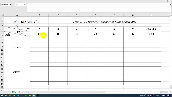
- 10. COM AL1 AL3 COM AL2 AL1 AL2 COM Non-C 24VAC/24VDC 50/60Hz 50/60Hz + – DI1 DI-COM CT1RSV1 + –RS485 Note 1: Power supplies for AL1 and AL2 must be of the same type, either AC or DC. Standard type 14 13 14 13 15 NO COM NC OUT1 14 13 – + COM OUT1 SSR SSR 14 13 + OUT1 COM – 14 13 – + COM OUT1 12 11 14 13 OUT1 OUT2 12 11 OUT2 14 13 15 NO COM NC OUT1 12 11 OUT2 – + COM OUT1 12 11 OUT2 14 13 14 13 + OUT1 COM – 12 11 OUT2 14 13 – + COM OUT1 14 13 15 14 13 15 14 13 15 14 13 15 14 13 15 14 13 15 14 13 15 14 13 15 14 13 15OUT2 COM OUT1 – + + OUT2 COM OUT1 – + + OUT2 COM OUT1 – + + OUT2 COM OUT1 – + + OUT2 COM OUT1 – + + OUT2 COM OUT1 – + + OUT2 COM OUT1 – + + OUT2 COM OUT1 – + + OUT2 COM OUT1 – + + OUT1 SSR SSR SSR SSR SSRSSR 17 16 18 17 16 18 17 18 17 18 6 5 6 5 8 7 10 9 10 9 10 9 Control output 1 Control output 2 Control output 1 Control output 2 Relay output (SPST) Relay output (SPDT) None None None None None VoltageCurrent Relay output (SPST) Relay output (SPST) Relay output (SPST) Relay output (SPST) Relay output (SPST) Relay output (SPST) Relay output (SPDT) VoltageCurrent VoltageCurrent VoltageCurrent VoltageCurrent or re-transmission output or re-transmission output or re-transmission output or re-transmission output or re-transmission output or re-transmission output Current or re-transmission output (current) Current or re-transmission output (current) Current or re-transmission output (current) Voltage or re-transmission output (voltage) Voltage or re-transmission output (voltage) Voltage or re-transmission output (voltage) 1 or 2 points3 points (Note 1) 2 points (independent common) Power supply Process value input Universal input RTD Current input Voltage input Thermocouple Remote SV inputDigital input CT input RS485 TERMINAL ALLOCATION Standard type
- 11. type Power supply Open COM Close 24VAC/24VDC Note 1: Power supplies for AL1 and AL2 must be of the same type, either AC or DC. COM + – A B B + – + – 17 16 18 17 16 18 17 18 17 18 5 4 6 2 3 1 11 10 12 8 9 7 17 16 18 14 15 13 100-240VAC 50/60Hz 50/60Hz 6 5 6 5 1 or 2 points2 points (independent common) 4 3 2 1 4 3 2 1AL1 AL2 AL2 COM AL1 COM AL1 AL2 COM Non-C (Note 1) DI1 DI-COM + –RS485 8 7 10 9 12 11 14 13 8 7 10 9 DI3 DI2 DI1 DI-COM Valve control output 1 Valve Control Valve Control Motorized valve control type Alarm output RTD Current input Voltage input Thermocouple Universal input Process value input Option Digital input RS-485 Digital input
- 12. on Safety *Before using this product, be sure to read its instruction manual in advance. Information in this catalog is subject to change without notice. Grobal Sales Section Instrumentation & Sensors Planning Dept. 1, Fuji-machi, Hino-city, Tokyo 191-8502, Japan http://www.fujielectric.com Phone: +81-42-514-8930 Fax: +81-42-583-8275 http://www.fujielectric.com/products/instruments/ Insulation block diagram Power Internal circuit Control output 1 (relay contact) or Motorized valve OPEN output Alarm output 1 (relay contact) Alarm output 1 to 3 (relay contact) Alarm output 2 (relay contact) Control output 2 (relay contact) or Motorized valve CLOSE output Process value input • When the 9th code is "J" AL 1 and 2: independent common : Basic insulation : Functional insulation : No insulation Digital input 1 to 3 Communication (RS-485) • When the 9th code is other than "J" AL 1 to 3: shared common Remote SV input CT input Control output 1 (SSR drive, current, voltage) Control output 2 (SSR drive, current, voltage)
|